| Crossover Cable | |
|---|---|
| RJ-45 PIN | RJ-45 PIN |
| 1 Rx+ | 3 Tx+ |
| 2 Rc- | 6 Tx- |
| 3 Tx+ | 1 Rc+ |
| 6 Tx- | 2 Rc- |
| Straight Through Cable | |
|---|---|
| RJ-45 PIN | RJ-45 PIN |
| 1 Tx+ | 1 Rc+ |
| 2 Tx- | 2 Rc- |
| 3 Rc+ | 3 Tx+ |
| 6 Rc- | 6 Tx- |
RJ-45 Ethernet Wiring Diag.
Discussion
|
|
|
||||||||||||||||||||||||
Please Note: The standard connector view shown is color-coded for a straight thru cable assembly, when connecting Hub to Xcvr or DNI Card. When connecting hub to hub, Xcvr to Xcvr, or DNI to DNI, the wires must crossover at the opposite end of the cable assembly.
CAT5 connectors look just like telephone connectors, only slightly wider, to allow 8 wires instead of 6. You can physically plug a 6-pin plug into an 8-pin socket, but it may damage pins 1 and 8 of the socket. Ethernet only uses 4 wires, but running 8 will save enormous time the first time a wire fails: you can just switch to another pair. Also, if no wires break you can split out the 8 into two sets of 4, and put 2 devices at the end of any wire (there are even handy adapters for this, like a one-to-two phone line adaptor; sadly they're not easy to find, but you can make one with a plug and two sockets). Or you may be able to use the other pairs for phone lines. However, I gather that the formal CAT5 definition reserves the remaining wires, so this is technically not allowed.
There are three wiring options, called T568A, T568B, and USOC. T568A is supposedly "preferred" (though I've heard that T568B may be more common), and looks like this:
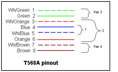
Or, in prose (and for accessibility), from pin 1 to 8 we have green/white, green, orange/white, blue, blue/white, orange, brown/white, brown. See also the wires in an actual plug.
Pair 1 is the blue pair, 2 is orange, 3 is green, and four is brown. So far as I know Ethernet protocols are not sensitive to insulation color, so if you scramble the pair assignments consistently you should be fine; but I wouldn't recommend it.
Only pair 3 (green, on pins 1 and 2), and pair 2 (orange, on pins 3 and 6) are actually used. So you can botch the other pairs and not get in trouble... until you want to use the other pairs to add a device without having to pull more wires through walls.
Old 10-base-t Ethernet specs called these pairs 1 and 2, on the apparent expectation that you wouldn't have any other pairs around. But pair 1 in CAT5 is the blue pair in the center, which is not used -- this is the same color and pins as for the primary telephone line wires, so avoiding it has the advantage of making it less likely that a telephone pair will get patched to an Ethernet pair (where the ringer voltage would probably cause lots of trouble).
CAT5 signals are "balanced": the striped and solid wires in a pair carry the same information negated, so their magnetic fields tend to cancel. Unlike phone wires, CAT5 wires do not cross over; the same wires go to the same pin numbers at all connectors. This works because hubs all have internal crossovers. Hub-to-hub interconnects need a special crossover cable, as does a hub-to-DSL-router connection, or a 2-node hubless network. See below for the details of making a crossover cable; if you make one, mark it so clearly that you'll never confuse it.
Be very sure you count the pins in the right order. Some connectors do not have pin numbers marked, though some are even better and are color-coded directly for T568A and/or T568B. If you get things backward they won't work (well, if you get everything consistently backward, maybe). You cannot swap wires across pairs (for example, to treat green and orange/white as a pair), since they are not twisted together, which is critical.
Warning: some sockets do not have the connectors in pin order, apparently because the sockets include internal twists for the same reason cable pairs are twisted. Mine go 21354687; but they're color-coded so you can ignore the pin numbers entirely. Make sure.
If you're looking into a socket with the latch downward, pin 1 is on your left.
If you're behind the socket with the latch downward, pin 1 is on the right.
If you're looking at the contact end of a plug with the latch down, pin 1 is on the right.
If you're looking at the wiring end of a plug with the latch down, pin 1 is on the left.
(Hint: Engrave "1" over pin one of the sockets on your tester)
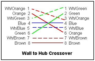
Crossover cables are used for hub-to-hub connections and for 2-machine networks with no hub (I carry one around for on-the-fly networking). Basically, a crossover cable swaps pairs 2 and 3 (not the wires within each pair); pairs 1 and 4 go straight through. This means one end is T568A and the other is T568B; there's probably some interesting history to that. So a crossover cable looks like:
If you use a punchdown block, the convention is to punch down the pairs in numeric order. In each pair the striped wire precedes the colored wire. Thus white/blue, blue, white/orange, orange, white/green, green, white/brown, brown (or "BLOG" for short: BLue, Orange, Green (brown is the one left over).
![]()